一、nRF52x移植工程到自己layout的板子上需要做如下配置
- 如果没有板载32.768kHz晶振,需要修改为内部晶振
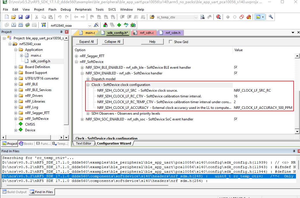
//使用内部晶振,推荐配置:应用程序至少8秒校准一次,温度每4秒变化0.5摄氏度 #define NRF_SDH_CLOCK_LF_SRC 0 //修改晶振为内部RC #define NRF_SDH_CLOCK_LF_RC_CTIV 16 //设置每4秒校准一次,0.25*16=4秒,校准定时器间隔,单位为0.25秒,范围为0.25-31.75秒 #define NRF_SDH_CLOCK_LF_RC_TEMP_CTIV 2 //如果温度恒定则设备可以(16*0.25)*2=8秒校准一次,即每4秒温度变化0.5摄氏度。 #define NRF_SDH_CLOCK_LF_ACCURACY 1 //设置晶振精度为500ppm - 如果没有串口可以打印log,需要开启rtt打印log

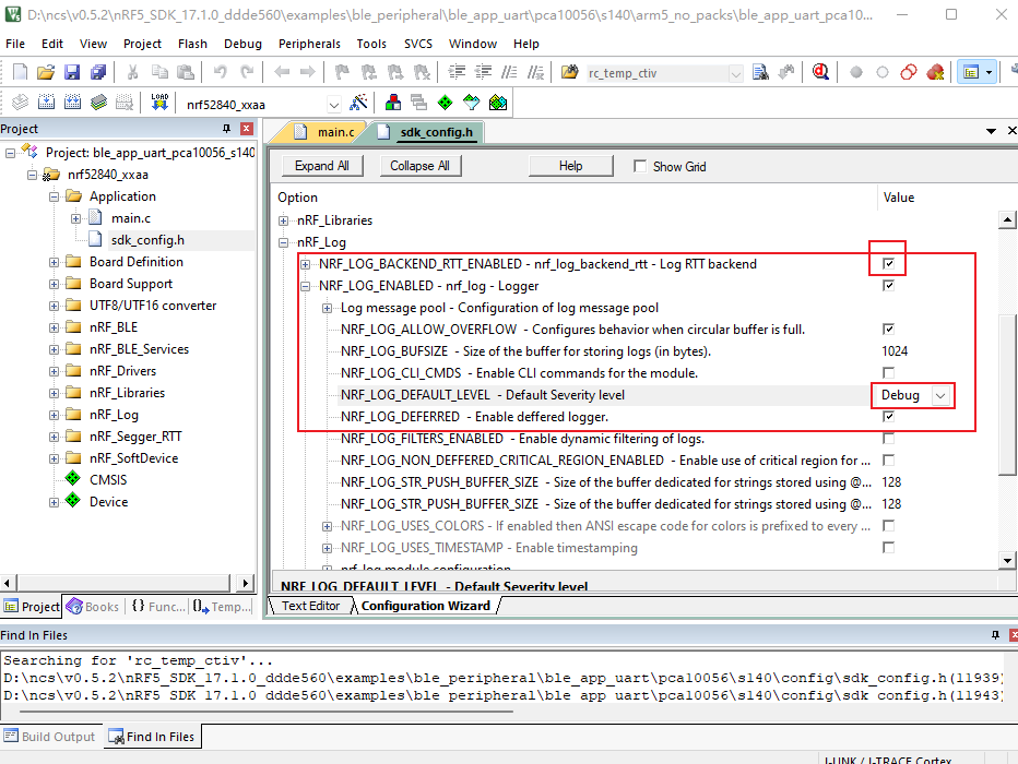
#define NRF_LOG_BACKEND_RTT_ENABLED 1 //开启rtt log #define NRF_LOG_DEFAULT_LEVEL 4 //开启debug模式 - 如果串口RX引脚悬空且没有配置上拉电阻则需要注释掉此部分代码
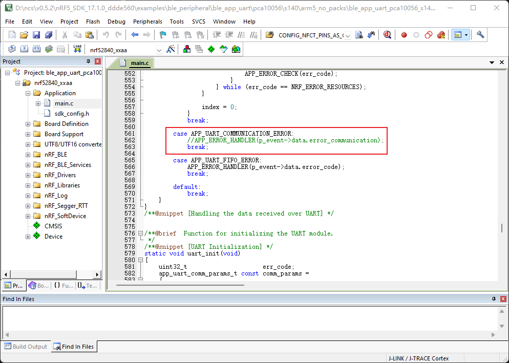
//APP_ERROR_HANDLER(p_event->data.error_communication); - 如果使用了复位脚作为普通IO口,需注释掉对应宏定义->完全擦除芯片->重新烧录程序
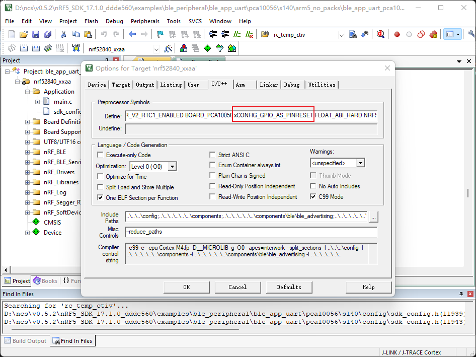
- 修改宏定义CONFIG_GPIO_AS_PINRESET ->xCONFIG_GPIO_AS_PINRESET
    /* Configure GPIO pads as pPin Reset pin if Pin Reset capabilities desired. If CONFIG_GPIO_AS_PINRESET is not
      defined, pin reset will not be available. One GPIO (see Product Specification to see which one) will then be
      reserved for PinReset and not available as normal GPIO. */
    #if defined (CONFIG_GPIO_AS_PINRESET)
        if (((NRF_UICR->PSELRESET[0] & UICR_PSELRESET_CONNECT_Msk) != (UICR_PSELRESET_CONNECT_Connected << UICR_PSELRESET_CONNECT_Pos)) ||
            ((NRF_UICR->PSELRESET[1] & UICR_PSELRESET_CONNECT_Msk) != (UICR_PSELRESET_CONNECT_Connected << UICR_PSELRESET_CONNECT_Pos))){
            nvmc_config(NVMC_CONFIG_WEN_Wen);
            NRF_UICR->PSELRESET[0] = RESET_PIN;
            nvmc_wait();
            NRF_UICR->PSELRESET[1] = RESET_PIN;
            nvmc_wait();
            nvmc_config(NVMC_CONFIG_WEN_Ren);
            NVIC_SystemReset();
        }
    #endif
- 如果使用了NFC管脚作为普通IO口,需要注释掉对应宏定义->完全擦除芯片->重新烧录程序
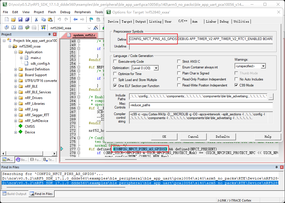
- 加入宏定义CONFIG_NFCT_PINS_AS_GPIOS
- 如果是bootloader文件需要用nfc管脚,则需要查看文件system_nrf52.c中,函数void SystemInit(void)中是否有如下代码,如果没有则要自己加入:
/* Configure NFCT pins as GPIOs if NFCT is not to be used in your code. If CONFIG_NFCT_PINS_AS_GPIOS is not defined,
 two GPIOs (see Product Specification to see which ones) will be reserved for NFC and will not be available as
 normal GPIOs. */
#if defined (CONFIG_NFCT_PINS_AS_GPIOS) && defined(NFCT_PRESENT)
 if ((NRF_UICR->NFCPINS & UICR_NFCPINS_PROTECT_Msk) == (UICR_NFCPINS_PROTECT_NFC << UICR_NFCPINS_PROTECT_Pos)){
   nvmc_config(NVMC_CONFIG_WEN_Wen);
   NRF_UICR->NFCPINS &= ~UICR_NFCPINS_PROTECT_Msk;
   nvmc_wait();
   nvmc_config(NVMC_CONFIG_WEN_Ren);
   NVIC_SystemReset();
 }
#endif
二、nRF52x移植工程到不同的官方开发板上需要做如下配置
- 可以配置的开发板有以下几种:
- BOARD_PCA10056
- BOARD_PCA10100
-
BOARD_PCA10040
- 可以配置的芯片型号有以下几种:
- NRF52805_XXAA
- NRF52810_XXAA
- NRF52811_XXAA
- NRF52820_XXAA
- NRF52832_XXAA
- NRF52833_XXAA
- NRF52840_XXAA
修改工程到不同开发板需要做以下更改
- 修改芯片型号为对应的芯片
- 修改板子为对应的板子
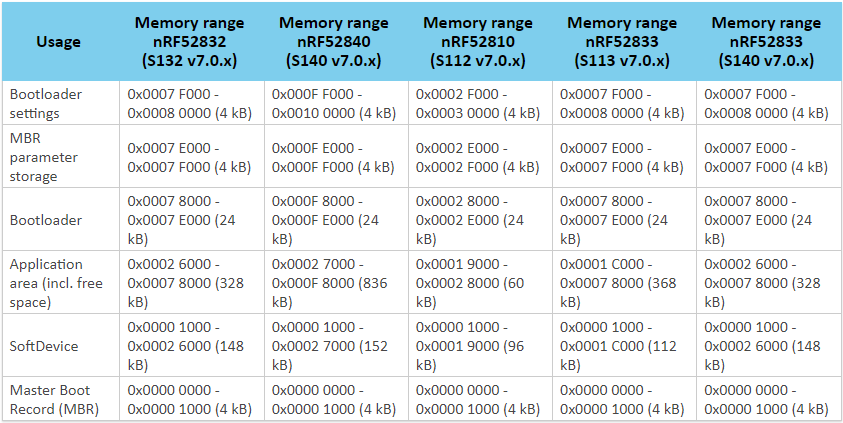
- 调整芯片ROM起始地址与大小 RAM起始地址与大小 参考文件:Memory layout
- When adding a bootloader to your device, you must be aware of where in the device memory the different firmware components are located.
The following table shows the memory layout for the different chips with current SoftDevices:
- The following figure shows the default memory layout for nRF52 devices, where nRF52832 has a flash size of 512 kB, nRF52840 has a flash size of 1024 kB, nRF52810 has a flash size of 192 kB, and nRF52833 has a flash size of 512 kB:
- Note: The size of the bootloader is fixed for the lifetime of the device. This is because the location (MBR_BOOTLOADER_ADDR) that stores the start address of the bootloader is not (safely) updateable. See the SoftDevice Specification for more information.

- When adding a bootloader to your device, you must be aware of where in the device memory the different firmware components are located.
The following table shows the memory layout for the different chips with current SoftDevices:
-
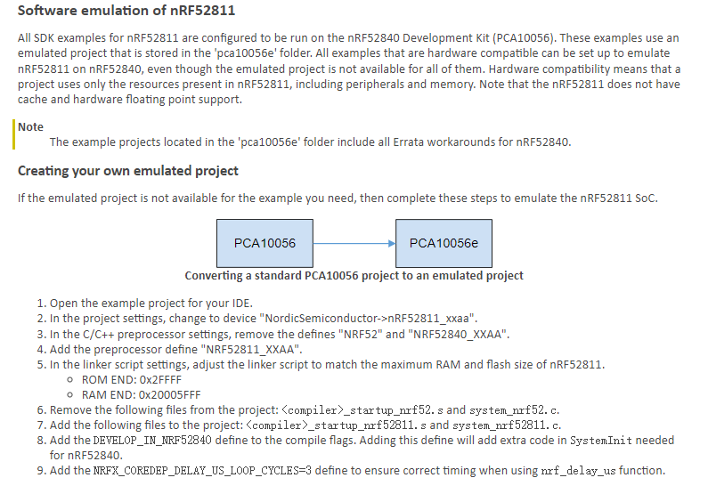
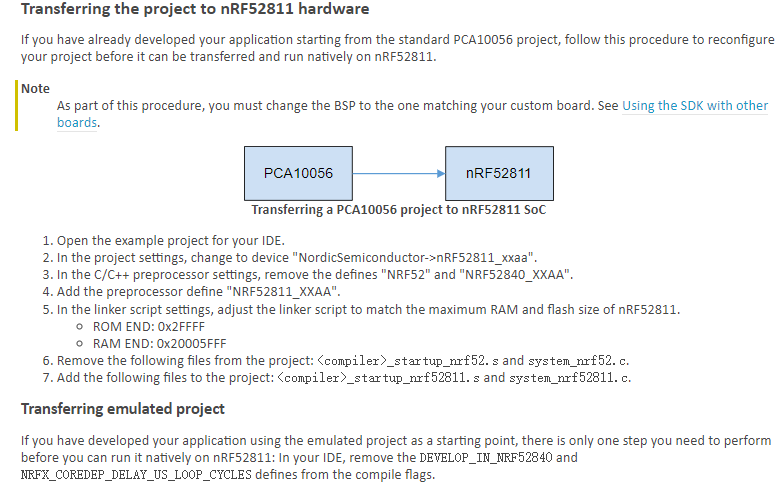
nRF52811开发需要做如下配置:参考文件:Developing for nRF52811
-
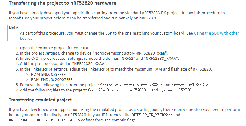
nRF52820开发需要做如下配置:参考文件:Developing for nRF52820

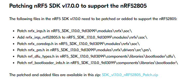
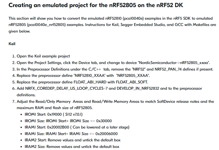
- nRF52805开发需要做如下配置:参考文件:[Developing for nRF52805
新手必知
海量第三方学习资源.
超全常用工具与文档.
本站常用资源下载.
常见问题搜索.
QQ群: 542294007.
文章引用自:元仓库 OLIB.cn.